Overview
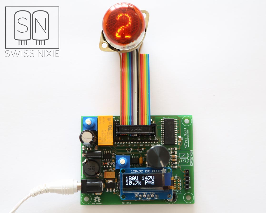
This is a self made testing device for nixie tubes with included power supply and measurement ability.
This project was mainly made from some components that were lying around in my workshop, so it might be not perfect, but used some components i already had. I need this tester for testing tubes, and to switch between the digits when taking pictures of tubes. I will make different cables connecting to tube sockets, so i can take pictures of tubes without the need to change aligator clips on the cathodes.
Functionality
The Tester has 15 individually controllable Outputs for the cathodes of a nixie tube. This allows testing all common tubes and even the 15-Segment B-7971 / B-8971 tubes. The cathodes can be selected by a rotary encoder that counts up or down in both directions.After startup there is no cathode active and the encoder must be turned once to count up one. With a potentiometer the needed anode resistor can be set directly on the board. The tester can also measure the anode-resistor, power supply voltage, and the voltage after the resistor
Display
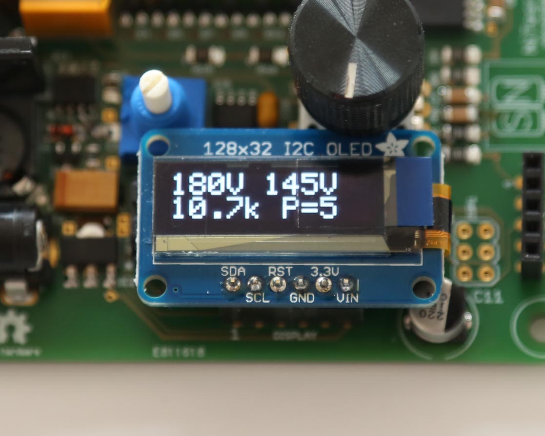
As Display i used a small 128x32 pixel OLED-Display made by Adafruit. Its very compact, sharp, bright and comes with a working arduino library.
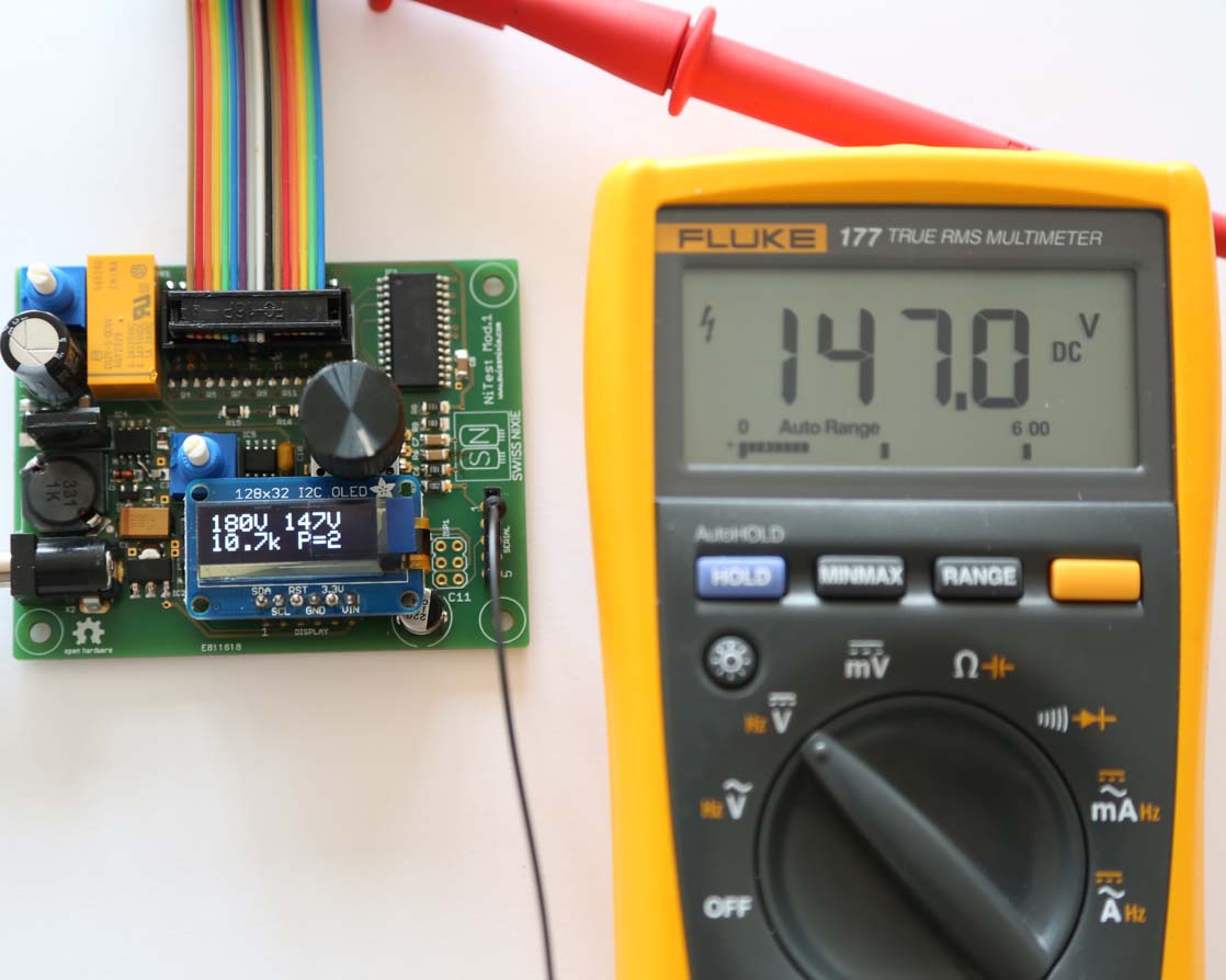
Here you can se a close-up of the display. The top left value is the power supply output voltage, the top right value is the voltage after the anode-resistor, the bottom left value is the last measured anode resistor in Kilohms and the bottom right value shows the current output that is switched on
Electronic Design
For the electronic design, i used mostly components that i already had.
The high voltage supply contains a step up regulator with the low-cost MC34043 IC. The output voltage can be adjusted with a potentiometer from about 160 to 230V DC, and deliver up to 25mA, which is more than enough for a single nixie tube. With a second potentiometer, a suitable anode resistor can be set.
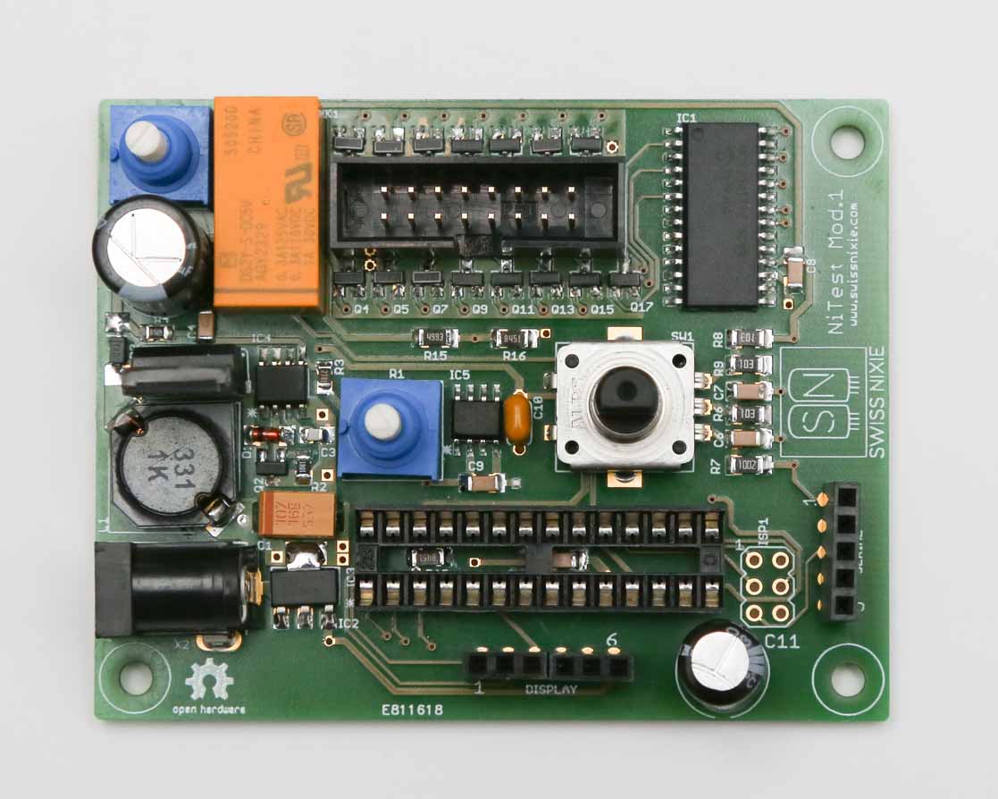
The microcontroller is a Atmega328 with arduino core. I wanted to use a Atmega168, but the librarys for display and the encoder used too much space, so i used a Atmega328. To save components, the controller runs on the internal 8Mhz oscillator. A rotary encoder with integrated button was used for controlling the cathodes and switching the display. The encoder can be turned left or right to count up or down, it does not matter in which direction the turning starts. After counting up to 15, it sets itself back to 0, because only 15 Outputs are possible. The selected number will be transfered to a MCP23017 port expander via IC2. High voltage mosfets are connected to the port expander outputs and will bring low the selected cathode, resulting in illumination of the connected symbol in the tube. If the encoder button is pushed for about one second, the controller will start the measurement of the anode resistor unless the button is released. After releasing the button a timeout will start and set the display back to normal. This allows to either push the button to check what the resistor is, or hold the button as long as needed to set the rigt resistor. The tube can be connected over a 16-pin connector, which allows to manufacture a cable for every type of tube.
Here you can see the assembled pcb and the schematic

Measurement and Accuracy
For the measurement of the anode-resistor potentiometer, i had to use a relais to take the potentiometer off the hv supply and connect it to a precision 4.096V Voltage Reference. If the relais is switched on, the potentio meter will create a voltage divider with a precision resistor and its output is connected to a analog input of the controller. The software calculates the resistance value from the measured voltage. The 50 Milliohm contact resistance of the relais can be ignored, because even a few hundred Ohms won't make a big change to the tubes brightness.
For the measurement of the two voltages, i used also voltage dividers with precision resistors (0.1% types) and directly connected them to an anlog input of the controller. The software calculates the input voltage of the divider, based on the output and the known resistors. Read more about resistor dividers here
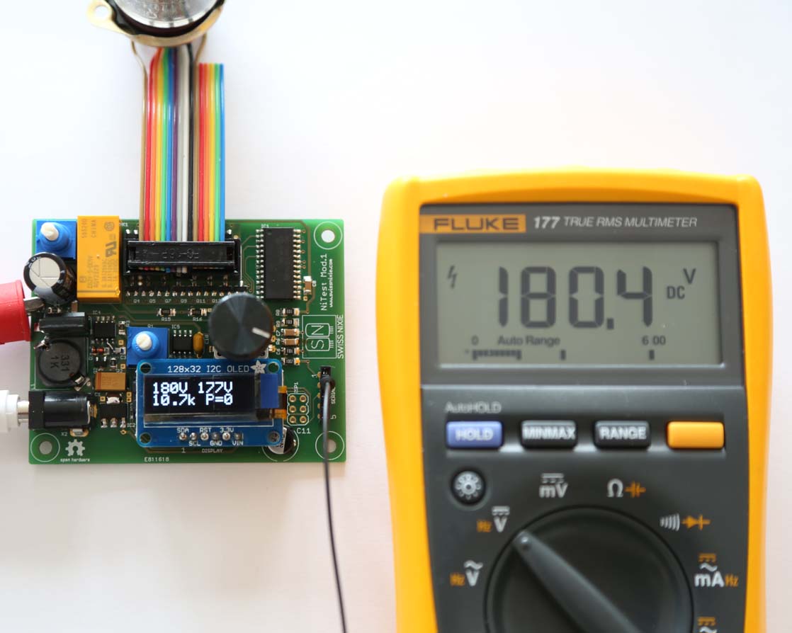
Against my thoughts, the result of these measures and calculations is about very accurate. It matches with a commercially made multimeter.Below you can see a comparision with a Fluke 177 Multimeter on the power supply output, and after the anode resistor when a tube is connected.
Case
I have not made a case now, but i will make one. It will be very simply and made of two pieces of transparent acryl material providing basic protection against touching hazardous parts.I don't need a full case since this tester is only operated in the lab.
Resources
Here are the design-resources like Eagle files and arduino code.
Eagle.zip Arduino.zip BOM (Partlist).xls